接續上一篇:
[教學文]你好,我會走路、唱歌跳舞跟偵測障礙物喔!——一起動手做超級卡哇伊的機器人OTTO97(上) ,讓我們繼續製作OTTO97機器人,一起來看接下來的步驟。
Step8:組裝左腿(連接擴充板 P15)
(1)打開 SG90 伺服馬達套件,會看見一顆伺服馬達、三支轉軸支架(旋臂),以及二長一短的螺絲。在此專案中,僅會用到最短的轉軸支架。
[caption id="attachment_24675" align="aligncenter" width="513"]
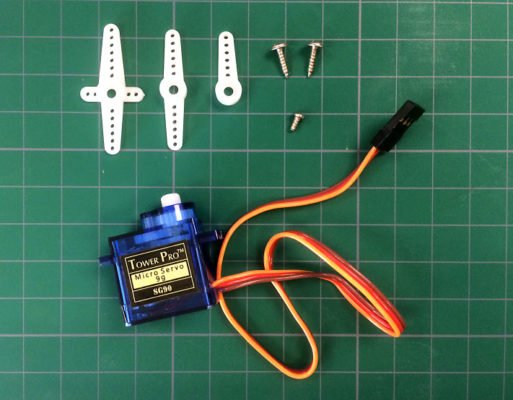
圖8-1[/caption]
(2)用兩隻長螺絲將伺服馬達鎖至OTTO身體的左腳位置。
[caption id="attachment_24676" align="aligncenter" width="465"]
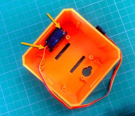
圖8-2[/caption]
(3)將伺服馬達接線至擴充板的
P15,並將手機上的LinkIt Remote APP連結至LinkIt 7697。開啟校正測試UI後,點選
Stiff按鈕使伺服馬達回到初始位置,亦即OTTO直立的狀態。
[caption id="attachment_24677" align="aligncenter" width="525"]
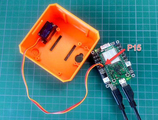
圖8-3[/caption]
(4)OTTO兩隻
腿的零件是相同的(但腳底板左右有分),因此可任意選擇進行組裝。
[caption id="attachment_24678" align="aligncenter" width="314"]
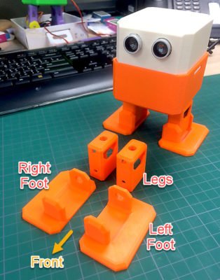
圖8-4[/caption]
(5)將轉軸支架切短以放入
左腿的卡榫溝槽(如圖8-5),並確認與伺服馬達的連接面需平整 (如圖8-6)。不平整的馬達接觸面將導致OTTO無法直線行走。
[caption id="attachment_24679" align="aligncenter" width="382"]
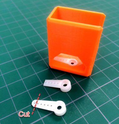
圖8-5[/caption]
[caption id="attachment_24680" align="aligncenter" width="607"]
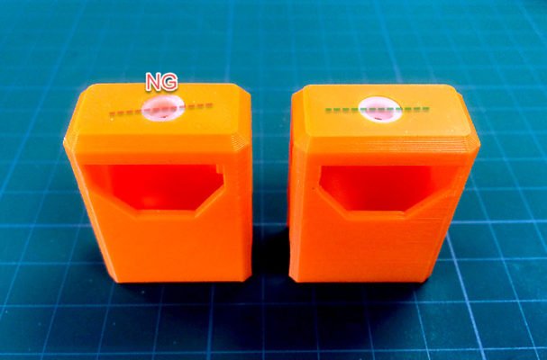
圖8-6[/caption]
(6)以面朝正面的方向(如圖8-7),將左腿連接至OTTO的身體。由於齒輪齒紋的關係,腿部不見得能精準對準身體正面,這可於之後的步驟透過校正測試 APP做修正。
[caption id="attachment_24681" align="aligncenter" width="556"]
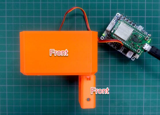
圖8-7[/caption]
(7)用短螺絲將腿上的轉軸支架與身體上的伺服馬達鎖緊,若沒有確實鎖緊會導致OTTO無法順利直線行走。
[caption id="attachment_24682" align="aligncenter" width="329"]
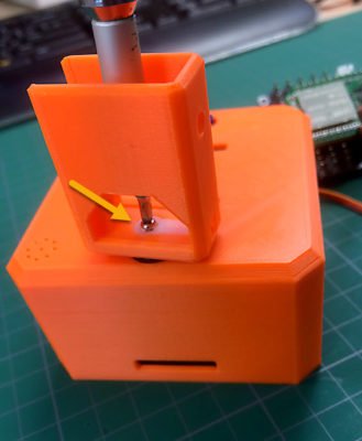
圖8-8[/caption]
Step9:組裝右腿 (P16)
(1)採用與組裝左腿相同的步驟完成右腿組裝,並將伺服馬達連接至擴充板的P16 接腳。
(2)開啟LinkIt Remote的校正介面進行腿部位置調整,使雙腿的初始方向平行於身體的面向 (如圖9-1)。校正完成後,務必按下Save按鈕儲存相關設定值供之後使用。
[caption id="attachment_24683" align="aligncenter" width="227"]
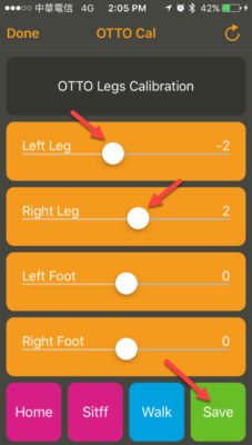
圖9-1[/caption]
[caption id="attachment_24684" align="aligncenter" width="623"]
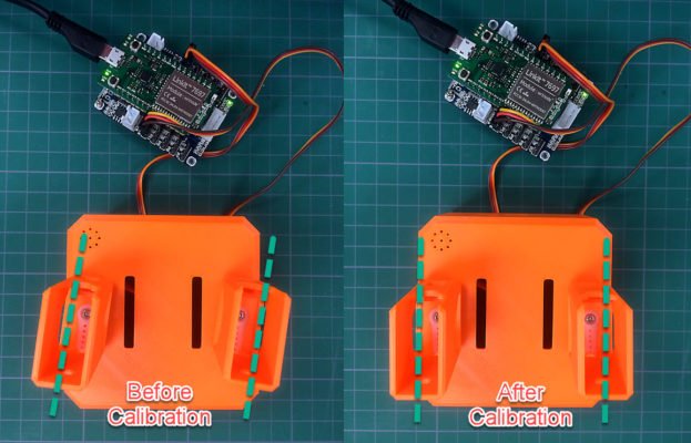
圖9-2[/caption]
Step10:組裝左腳底板(P5:LF)
(1)將伺服馬達的電線穿過左腿及身體的開孔後連接至
Robot Shield的
P5。
[caption id="attachment_24685" align="aligncenter" width="549"]
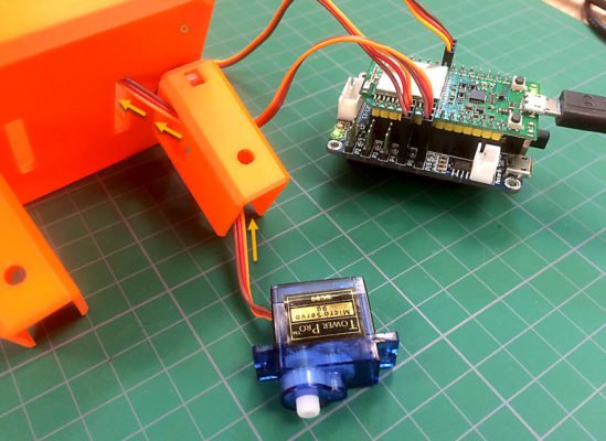
圖10-1[/caption]
(2)選擇校正介面中的
Stiff ,將伺服馬達轉軸置於初始位置。
[caption id="attachment_24686" align="aligncenter" width="225"]
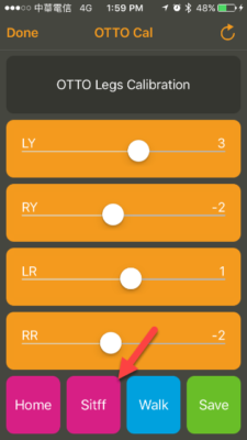
圖10-2[/caption]
(3)切割馬達轉軸支架(懸臂),使它能放進
左腳底板零件的卡榫溝槽。
[caption id="attachment_24687" align="aligncenter" width="567"]
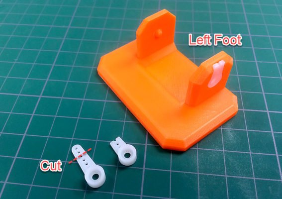
圖10-3[/caption]
(4)用短螺絲將伺服馬達鎖緊固定於腳底板上。
[caption id="attachment_24688" align="aligncenter" width="414"]

圖10-4[/caption]
(5)整理並反折馬達的線,好將馬達放入
左腿的機構中。
[caption id="attachment_24689" align="aligncenter" width="711"]
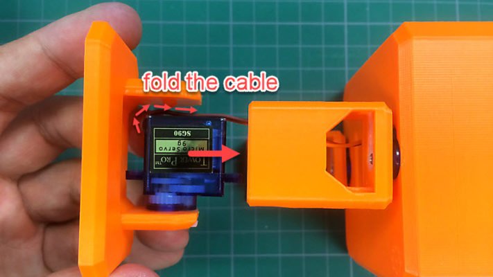
圖10-5[/caption]
[caption id="attachment_24690" align="aligncenter" width="334"]
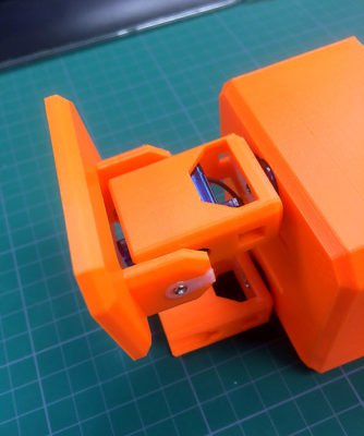
圖10-6[/caption]
(6)用長螺絲鎖緊固定馬達和左腿(注意正反面,下圖為OTTO的背面)。
[caption id="attachment_24691" align="aligncenter" width="310"]
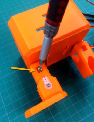
圖10-7[/caption]
Step11:組裝右腳底板(P11: RF)
(1)依照與組裝
左腳底板相同的步驟,完成
右腳底板的組裝,並連接伺服馬達至擴充板的
P11。
(2)使用校正APP調整腳底板的角度,使它們能平穩站在地面上(如圖11)。
(3)矯正完畢後,務必點選
Save儲存相關設定值。
[caption id="attachment_24692" align="aligncenter" width="657"]
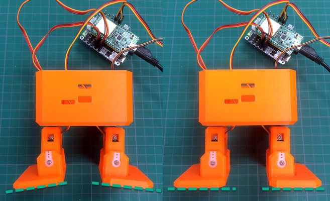
圖11[/caption]
Step12:
將Robot Shield裝進OTTO身體內
(1)為留下安裝LED模組的空間,將Robot Shield放進OTTO身體時,盡量將腿部相關走線整理至後方(如圖12-1中,綠色箭頭所指方向)。
[caption id="attachment_24693" align="aligncenter" width="393"]
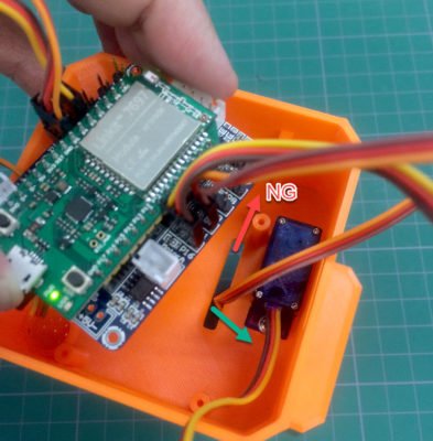
圖12-1[/caption]
(2)調整Robot Shield位置,使開發板相關接口能對齊OTTO身上預先開好的孔位。
[caption id="attachment_24694" align="aligncenter" width="376"]
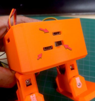
圖12-2[/caption]
(3)使用Robot Shield附贈的螺絲,將板子固定在OTTO身體機構中。
[caption id="attachment_24695" align="aligncenter" width="357"]
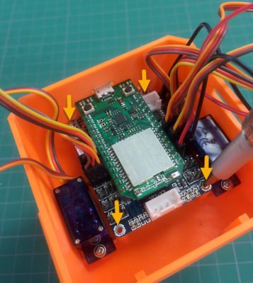
圖12-3[/caption]
Step13:安裝超音波感應器、蜂鳴器及8x8矩陣式LED
(1)接下來的組裝步驟,會依照圖13-1的接線方法,分別將之前測試過的超音波感應器、蜂鳴器及8x8矩陣式LED,連接回Robot Shield。
[caption id="attachment_24696" align="aligncenter" width="382"]
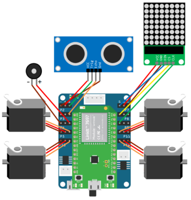
圖13-1[/caption]
(2)將蜂鳴器面朝下安裝至OTTO身體中預留的蜂鳴器位置,並將接線接回
Robot Shield。
[caption id="attachment_24697" align="aligncenter" width="405"]
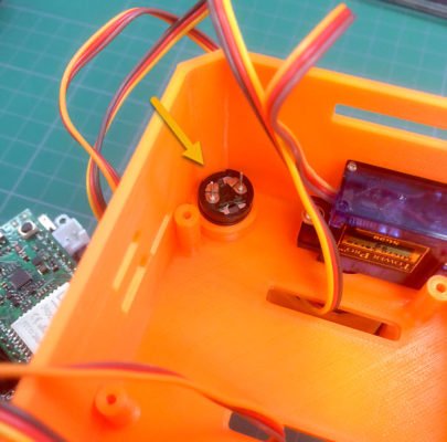
圖13-2[/caption]
(3)將超音波感應器模組安裝至OTTO的頭部內(可用銼刀修整眼睛開口邊緣,以方便安裝),並將接線接回至
Robot Shield(注意
Trig/
Echo接線的位置)。
[caption id="attachment_24698" align="aligncenter" width="357"]
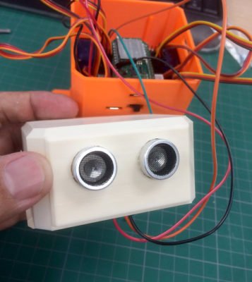
圖13-3[/caption]
(4)將8x8矩陣式LED模組接線回Robot Shield,並以膠帶或其它絕緣物包覆LED模組背面,以避免接觸Robot Shield造成短路。
[caption id="attachment_24699" align="aligncenter" width="331"]
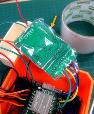
圖13-4[/caption]
(5)放置LED模組於OTTO身體正面位置(如圖13-5箭頭所指)。
[caption id="attachment_24700" align="aligncenter" width="314"]
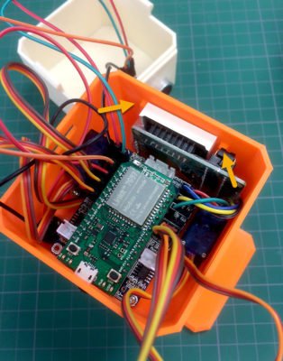
圖13-5[/caption]
(6)最後將
頭部和
身體組合起來,就完成了OTTO的組裝。
[caption id="attachment_24701" align="aligncenter" width="307"]
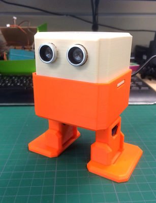
圖13-6[/caption]
Step14:執行Demo App
(1)在Arduino IDE中開啟
OTTO_Demo.ino範例,並上傳至LinkIt 7697執行。
(2)開啟LinkIt Remote APP並連接至OTTO,從LinkIt 7697載入UI後,會看見如圖14-1的控制介面:
[caption id="attachment_24702" align="aligncenter" width="225"]
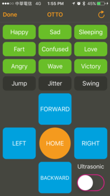
圖14-1[/caption]
接下來就可開始嘗試OTTO各式各樣的動作了!
閱讀完了全文,讀者們是否很想趕快動手組裝一台OTTO97機器人呢?若讀者們想購買LinkIt7697 + Robot shield等相關開發板,歡迎前往
機器人王國挑選,謝謝。
相關文章
留言 💬 (0)
還沒有留言,來當第一個。